

Getting ready to bake a transistor infused Raspberry Pi

HEALTH WARNING
This is a post in progress. Also note I’ve burnt my fingers several times and I live in constant fear of burning out my Pi, so if you do decide to follow along, I suggest do so but do your own learning & be prepared to break things!
OK, so this week the core plan is to understand the basics of what I’m doing with my Raspberry Pi. Its worth noting I was pointed to several excellent blog posts of folks that have built something very similar to what I am intending to build (e.g. autopatzer). But the core of what Im doing here is to build this myself, so lets see how far I get along before I start copying peoples homework extensively.
My plan this week is 1/ Understand the GPIO ping layout of the Raspberry 5. 2/ Control the basic elctronics that I will need to control.
The Raspberry Pi is an amazing little linux based computer that can be turned to do lots of mundane and fun things around the house. One favorite of mine was the kano project that was a mini child friendly computer that taught kids the basics of terminal commands vi games and got them hacking minecraft. In the early days of GPT I had near success using my raspberry pi 4 as a chromecast video forwarder so that I could send PS5 images and videos to the TV on the other side of the room. The reason I say near success was, GPT was able to get me video across but the lag was just not bearable for playing video games. I suspect its possible but havent got back to that project. Anyhows I digress, Raspberry PI is a cool bit of kit but in this project I need to control external electronics so that leads me down the rabbit hole of the cool PINs.
GPIO Pins
The Raspberry PI 5 comes with 40 Pins, that basically enable you to control stuff from the board directly. Now attaching stuff to the pins directly is kinda crazy, as you prototype you will want to use what’s called a breadboard to make building random circuits without soldering “easy”, and if you buy a cobbler it will make linking the PIs pins to the board to a degree, foolproof (but look up resources on how to attach the cobbler!)
Here is the stuff I bought from Amazon to get me going (affliate links below).
1/ A breadboard and some jumper wires : so that I can wire leds and what not easily and experiment with stuff (I already have a bunch of LEDs, motors and stuff).
2/ A cobbler so that I can connect my Raspberry Pi Pins to the breadboard in a easy way.
3/ A multi-meter so that I can test voltage, resistance and current around the circuits I build.
Now down to the hard bit, pinout.xzy provides a nice resource on the different names of pins and the pi site gives a good intro but while the pictures are nice I’m still very-very lost! So lets work out what all these different pins mean.

There are the following types of pins and acronyms The easy ones
1/ 3v & 5v power (pins 1 & 17 are 3V and 2 & 4 are 5V): These positive side of the DC supply power, be especially careful of wiring these pins into circuits other than ground.
2/ Ground (pins 9, 25 39, 6, 14, 20, 30 & 34 ) these are the ground of negative of the power source. Using these in conjuction with 1/ complete the circuit. using these you can prototype simple circuits, which is nice before you get any code into the mix. It’s also nice to work out whats meant to go on, before you start bringing the programatic pin’s into the mix!
Now the interesting ones
3/ All other pins are GPIO (General Purpose Input/Output) (pins 3,5,7-8,10-13,15-16,18-19,21-24,26-29,31-33,35-38,40). These pin can be driven by software as either 3.3V input or output. (I will touch the software later).
- When used as output, the pin when code is invoke will drive positive charge from this pin, and so when wired to ground it can be used to selective send current down to the recieving ground or another GPIO pin set as input. Handy for lighting LED’s.
- When used as input, if positive charge (careful of the 5V power!) the pin act as a ground and can invoke code/logic when power current is sent to it.
Some of these GPIO pins have extra capabilities, one of these capabilities will be important for what we do, Pulse Width Modulation.
- PWM (Pulse Width Modulation). There is dedicated hardware support for PWM on GPIO 12, 13, 18, 19 (pins 32,33,35,12) and PWM can be driven by software on all other pins. Basically you can vary the power sent to the device by turning the signal on and off really quickly. This is more effecient than trying to dynamically change the voltage. This capability is useful for controlling the brightness of an LED, the changing the speed of a motor or how strongly an electro magnet is on. Most certaintly I will be using this capability in my chess board. The dedicated support (as opposed to software control) enables more precise control and removes CPU overhead in controlling the rapid switching on-off-on.
As per other things the PI can do there are many, from what I see mostly these are about data exchange protocols (Im stretching this a bit to include digilat to audio). But for my needs I don’t (think) I really need to worry about them. For completeness I have included them here.
- PCM (Pulse Code Modulation) There are 4 GPIOs involved here 18, 19,20,21. PCM is used for digital to analogue audio conversion. Im not going to go into detail here (because I dont seeit being useful for the chess board but this is what I understand)
- 18 (PCM_CLK) Clock: The role of the clock is simple, its the drum beat of information about what time it is.
- 19 (PCM_FS) Frame Sync:: The frame sysnc is in control of when different channels come into play (think stereo sound with left and right). It inidicates when the start and end of each frame will commence and end.
- 20 (PCM_DIN) Digital In :: This is digital in, obeying the protocol agreed with the frame sync.
- 21 (PCM_DOUT) Digital Out :: This is digital out, again obeying protocol agreed with the fraem sync.
Pins 3 & 5 (GPIO 2 and GPIO 3) have what have the modification SDA and SDC respectively
- SDA means Serial Data and SDC means Serial Clock. From what I understand these are useful if you want to communicate to other devices (that use a standard called I2C). The “clocks” job is to basically keep messaging “in-sync”, think of it like a drum beat, and the data is the bits of data that are being passed across the interface during that time. This binary signal is enabled via a a dedicated “fixed pull-up resistor”. The other pins enable pull up resistors via software. Running the pull-up resistors in hardware, make ths signal more consistent, requires less compute and energy overhead to run and can be faster all of which as important if your using it to run a data bus. This is all nice to know, but I don’t think this will influence my chess board.
SPI (Serial Protocol Interface) There are two of these on the raspberry pi, each controlled by 4 lines. These are used for driving things like displays or memory cards. each made up of a CLK (Clock), a MOSI (Master Out Slave In), MISO (Master In Slave Out), The devices can be selected via the CE lines (CE0, CE1, CE2). A binary signal is sent to the CE line to let it know its “on”.
TX/RX Transmit / Receive: These are lines that cant be used to drive UART (Universal Asynrcronouse Receiever/Transmitter).
ID ID_SC ID_SD (ID Serial Clock & ID Serial Data), these pins are used by the raspberry pi to identify what Raspberry Pi calls HATs. These bold on devices add additional capability to the PI. On boot up, if a HAT is attached data is transmitted and sent to the HAT to help self configure it and identify which of the GPIO pins the HAT will use.
ElectroMagnets and Transistors
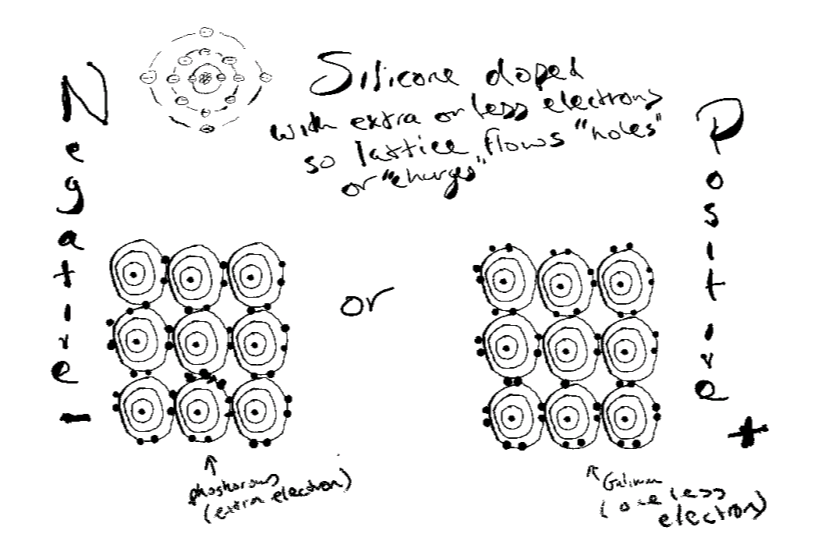
To move the chess pieces the plan is to use an electro magnet to attach to a chess piece under the board and then move it using the 2-plotter (controlled by two servos). To get that working I need to use a transistor. Now I ended up utterly confused and derailed on this for several weeks, because if there are lots of symbols on a GPIO breakout, there is a tonne load more on the info card for a transistors. Then there are loads of different types of transistors, NPN, PNP and I also looked a little at MOSFETs. I was guided by a reliable source to look at NPN’s and it turned out I had a few P2N2222A transistors sitting in an old ardunio kit I bought. Transistors work by taking the semi-conductor silicon, that has 1/2 its outer shell filling and doping it, so that there are either extra electrons (Negative) or fewer electrons (Positive) by introducing other elements (phosphorous for negative and galeon for positive). Then a sandwhich is made NPN (negative positive negative). When current is added to the center (the base), it enables the current to flow across the sandwhich as (I assume) extra electrons are added to the P layer.
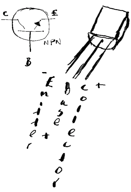
Now, given I’d decided to use and NPN transistor. The idea is the main load (my electro magnet) power on the 5v line of my Pi would be turned on and off by the GPIO pins which run 3.3v. The load is connected before the collector of the NPN and the emmitter of the NPN is wired to ground. The challenge is how much voltage and current to send to the base pin?.
The circuit I am building towards looks like this.
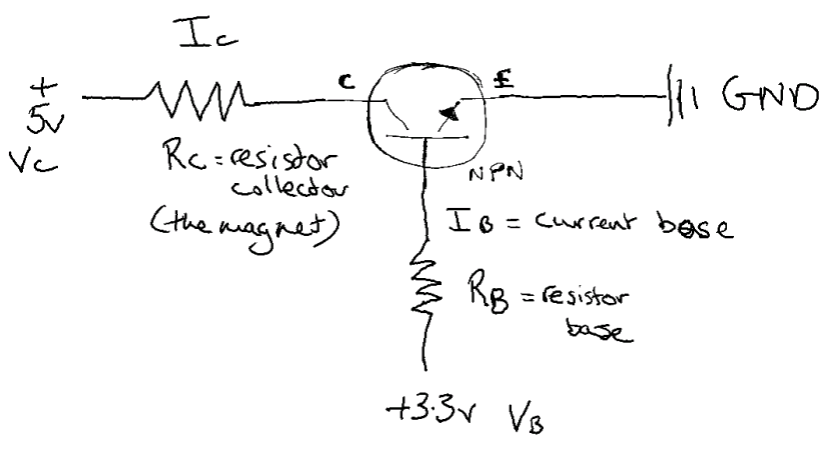
To work out the $R_B$ and $I_C$ I was helped by this nice video. In particular the following steps.
- Wire the 5V circuit without the transistor,and using a multi-meter identify the current that the load (the electro-magnet $R_C$ ) is drawing. I found this to be 0.33 Amps (lower than the 0.4 Amps I needed (see learnings below).
- Now the current that is needed on the base $I_B$ needs to be a multiple known as the current gain, $ \beta $. This can be found on the data sheet of your transistor, mine was P2N2222A. This was confusing, as many values are given, but I settled on a $ \beta $ of ~60. This leads to a $I_B$ of ~0.0055 Amps (5.5 mA).
- Now back to the data-sheet, the base needs driven by a small amount of voltage. Too high and your transistor will get hot (I burnt my finger!), and if is far to high it will break down. I see on the data sheet that the base saturation voltage is between 0.6V and 1.2V, I chose 0.7V
- So now a bit of Ohms law ( $ V = I * R $ ), to work out the resistor value to get the correct draw of current. $ R_{base} = (3.3 - 0.7) volts / 0.0055 amps $, leading to a resistor of $ ~450 \Omega $
Learnings
-
Current is shared After a bit of mishap wiring, I observed when the transistor was on I was drawing slightly less than the 0.33 Amps previously. This is because, current available from the Pi 5 (~0.33 Amps) is shared across all the pins. So the current from the base, reduced the amount of current available over the transistor.
-
I need more 💪 I will need an external power supply to provide enough 0.4 Amps current to the electro-magnet. After trying the strength of the 10kg electro magnet though the perpex chess board top (using 0.33 Amps) I’ve decided I need to beef up to a 25 kg magnet. Both these are now in the post to me (25 kg electro magnet & 5v 20A power supply).
Stepper Motors
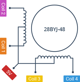
Stepper motors allow for precise control of rotation, and so provide a precision way to move rails in one direction or another. I happen to have a stepper motor from my old ardunion kit, its a 28BYJ-48 - 5V Stepper Motor It also came with a driver. I also purchased a couple of additional stepper motors and drivers CX28BYJ48-08. Similar to transistors it’s pretty cool how these work.
28BYJ-48 engine (with gear)
- torque at the gearbox output: 0.3 kg * cm (0.03 Nm)
- gear ratio: 64: 1
- rated voltage: 5V
- current consumption per coil: 100 mA
- coil resistance: 50Ω
- pins: five wires
- shaft diameter: 5mm with cuts
- weight: 35g
- distance between mounting holes: 35mm
- dimensions: ϕ28 x 19mm (without shaft)
- cable length: approx. 24 cm
The 28BYJ-48 has two coils, each of which has a center tap. These two center taps are connected internally and brought out as the 5th wire (red wire).
- 15 rotations per minute.
- Torque :: 34.3 mN.m
######
Bits to buy
Hall Effect Transistor (A1120EUA-T)
Hall Effect Transistor 3.3v Buy from here